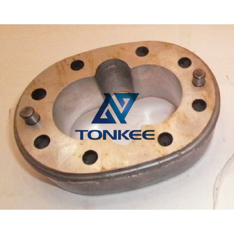
Model: The 5C1 26011101A05 is a specific model of hydraulic gear pump designed for various hydraulic applications.
Flow Rate: The flow rate of this pump is a critical specification and typically ranges from [specify flow rate] liters per minute (LPM) to [specify flow rate] LPM or gallons per minute (GPM) depending on the manufacturer's specifications. The flow rate determines how much hydraulic fluid the pump can deliver per unit of time.
Pressure Rating: Hydraulic gear pumps are designed to handle specific maximum pressures. The 5C1 26011101A05 may have a pressure rating of [specify pressure rating] bar or psi, which indicates the maximum pressure it can generate within a hydraulic system.
Mounting: This pump is designed for specific mounting configurations, and it's important to ensure that it matches the mounting requirements of the hydraulic system it will be installed in.
Material: The construction of the pump typically involves high-quality materials such as cast iron or aluminum, which provide durability, resistance to wear, and protection against corrosion.
Seals: Hydraulic gear pumps like the 5C1 26011101A05 rely on seals made from materials like rubber or elastomers to prevent fluid leakage and maintain the integrity of the hydraulic system.
Port Size: The pump is equipped with inlet and outlet ports of specific sizes, usually measured in inches or millimeters, to connect to the hydraulic system's hoses or tubing.
Functions:
The primary function of the 5C1 26011101A05 hydraulic gear pump is to convert mechanical energy into hydraulic energy, which can then be used to power various hydraulic functions.
Here's how it accomplishes this:
Input Shaft: The pump is typically connected to a power source, such as an electric motor or an internal combustion engine. This power source drives the pump's input shaft.
Gear Mechanism: Inside the pump, a pair of interlocking gears (the "drive gear" and the "driven gear") work together to create sealed chambers. As these gears rotate, they trap and move hydraulic fluid.
Inlet Phase: When one of the gears rotates, it creates a low-pressure area in the pump's inlet. This causes hydraulic fluid from the reservoir to be drawn into the chamber through the inlet port.
Compression Phase: As the gears continue to rotate, they move closer together, compressing the trapped fluid. This compression increases the fluid's pressure.
Outlet Phase: When the gears reach a point where they separate again, the pressurized hydraulic fluid is forced out of the pump through the outlet port.
Flow and Pressure: The pump's rotation and gear design determine the flow rate and pressure generated. This hydraulic energy can then be used to power various hydraulic functions in equipment or vehicles, such as lifting, steering, or braking.