Model: The 5C1 40061PTO is a specific model of hydraulic gear pump, designed for power take-off (PTO) applications.
Flow Rate: It is essential to consider the flow rate when selecting a hydraulic gear pump. The 5C1 40061PTO typically has a flow rate of [specify the flow rate] liters per minute (LPM) or gallons per minute (GPM), depending on the manufacturer's specifications.
Pressure Rating: The hydraulic gear pump is designed to handle a certain maximum pressure. The 5C1 40061PTO may have a pressure rating of [specify the pressure rating] bar or psi.
Mounting: This pump is typically mounted to a PTO connection on a vehicle or hydraulic system. The mounting method should match the PTO system's specifications.
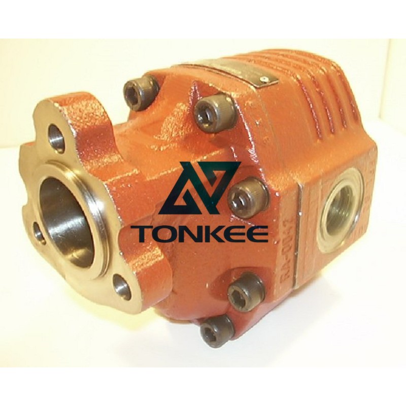
Material: The pump is constructed from high-quality materials, often featuring cast iron or aluminum components. These materials provide durability and resistance to wear and corrosion.
Seals: Hydraulic gear pumps like the 5C1 40061PTO use various seals to prevent fluid leakage. These seals are typically made from rubber or other elastomeric materials.
Port Size: The pump will have inlet and outlet ports of specific sizes, typically measured in inches or millimeters, to connect to the hydraulic system's hoses or tubing.
The primary function of the 5C1 40061PTO hydraulic gear pump is to convert mechanical energy from a power take-off (PTO) source into hydraulic energy. Here's how it accomplishes this:
Input Shaft: The pump is connected to the vehicle or equipment's PTO, which provides mechanical power when engaged.
Gear Mechanism: Inside the pump, a pair of interlocking gears, often referred to as the "drive gear" and the "driven gear," work together to create a sealed chamber. As these gears rotate, they trap and move hydraulic fluid.
Inlet Phase: When one of the gears rotates, it creates a low-pressure area in the pump's inlet.
Hydraulic fluid from the reservoir is drawn into this chamber through the inlet port.
Compression Phase: As the gears continue to rotate, they move closer together, compressing the trapped fluid. This compression increases the fluid's pressure.
Outlet Phase: When the gears reach a point where they separate again, the pressurized hydraulic fluid is forced out of the pump through the outlet port.
Flow and Pressure: The pump's rotation and gear design determine the flow rate and pressure generated. This hydraulic energy can then be used to power various hydraulic functions in equipment or vehicles, such as lifting, steering, or braking.
Agriculture: Used in tractors and agricultural machinery to power implements like loaders, plows, and hydraulic cylinders.
Construction: Employed in construction equipment for tasks like lifting and tilting buckets, as well as controlling outriggers and stabilizers.